info@zerringer.com
toronto.office@zerringer.com
Ken N. Burn
The discussion that follows is an expanded version of the talk presented by Ken Burn during the Building Science Insight program. Stone is said to represent the epitome of durability and since there is a reviving interest in the use of stone, particularly as a facade material, it seems appropriate to gather material pertaining to this technology and to present an update on historical development and some fundamentals of the use of stone on our new buildings. This presentation is of particular interest to designers, as it brings to the fore the little-known problems associated with the use of stone as a veneer.

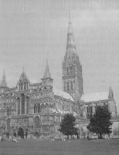
Pic.1
Without question, the most enduring human works are those constructed of stone. Archeologists have found organic remains of a Woodhenge on Salisbury Plain which predates the surviving monument, but it is the massive stone blocks and lintels placed about 3,500 years ago that remain to form the famous landmark known as Stonehenge (Pic. 1).
The construction of the pyramids around the same time involved a series of more ambitious projects. The cutting and shaping of stone, which permitted closer fitting of pieces, was greatly advanced because of the development of metal tools in Egypt.
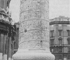
Pic.2
Beautiful temples and other structures were built in Egypt, and later in Greece and Rome and throughout the Roman world, with stone fitted with a high degree of precision and intricately carved (Pic. 2).
Pic.3
The Middle Ages saw the building of massive defensive structures in the form of castles, and of lofty church spires, reaching to a maximum of about 160 m above grade (Pic. 3). These heights were limited not by the material but by building technology and foundation conditions. The compressive strength of most stone far exceeds any load that it has been called upon to carry. The Washington Monument, for instance, 170 m high, with walls 4.5 m thick at the base, develops compression stresses at foundation level of something like 4 MPa, which is high, but is only 1/25 of the compressive strength of the stone.
The technology of building in stone, basically one of providing bearing walls and columns to carry floors and roofs, was not changed, except in style and sophistication until the advent, in the mid-nineteenth century, of steel and reinforced concrete building structures. Walls no longer needed to be massive at the base; curtain walls thinner and lighter than before became possible and with the same weight on the foundations several more stories could be added.
The first skyscrapers (higher than 15 stories) were built in Chicago and the new technology was picked up and advanced in New York City, where much better foundation conditions allowed heavier loads, so that even taller buildings could be constructed. Thinner stone was used to face the buildings, but the detail of the outward appearance was much the same. Blocks were laid on top of one another and held in place by metal fastenings to, and by interlocking courses with, backup walls of less expensive and lighter masonry materials such as brick, clay tile and concrete or cinder-block. Careful testing and improvement of production techniques allowed higher stresses in steel and reinforced concrete, and advances in analysis of structural frames and a better understanding of their responses to loads allowed buildings to reach further skyward.
Concrete, the artificial stone, was already making inroads into an ancient industry before the Second World War. It was imagined that it could be made into any desired shape and be produced almost anywhere. The color and texture of surfaces, it was thought, could be selected at will from an endless variety of possibilities.
Steel and other metals could be formed in thin sheets and fitted into metal frames with glass to form lightweight curtain walls. War production had introduced the new plastic materials and had resulted in an enormous increase in the production of aluminum and its new, stronger alloys.
By comparison, stone, still quarried in much the same way as it had always been, and lacking the flexibility of the new manufactured materials, became relatively expensive and after the Second World War its share of the building material market went into a steady decline. Use of cut stone, however, did continue for prestigious buildings, particularity in lobbies and, if not for the main facade, at least around the main entrance. But it appeared that its principal use in the future would be limited to monuments or as crushed stone for road construction and concrete and asphalt aggregates.
Stone, however, has two great advantages over most other building material. Like wood, it does not have to be manufactured and it has a proven record of high resistance to weathering. In addition, stone exists in textures and colors that cannot be duplicated by any other materials. These very desirable properties of stone and the continued wish to use it in buildings, even at a premium, caused new techniques to be developed, both in preparing the stone and in construction. Stone is now being cut into thin slabs and these are used to face precast concrete panels and light metal frames in a variety of ways. One of the major economic factors in this is the large increase in the area of wall that can be clad from one quarry block.
It isn’t essential for purposes of this discussion, but it is useful to know something about the origin and subsequent geological history of particular types of rock because these factors largely determine strength, porosity, workability, hardness and other physical and chemical characteristics which influence their behavior as a building material. In addition, these factors impart texture, fabric and color, which define appearance, a major factor in selection. Stone, of course, derives from rock, and a distinction is made between the two forms, “rock” being the natural material in place in its geological formation, and “stone” being pieces of the parent rock physically separated from it, usually for commercial purposes. The pieces may be small, water-worn to form gravel or mechanically broken to form crushed stone. Cut into blocks and thin panels suitable for buildings, it is often referred to as “dimensioned stone”.
Geologists distinguish between three main groups of rocks on the basis of their origin: 1) igneous rocks, which include the granites; 2) sedimentary rocks, such as limestone and sandstone; and 3) metamorphic rocks, such as marble and slate.
Granites were formed by the slow cooling of molten rock or magma deep within the earth’s crust; they are characterized by coarse, crystalline grains of the constituent minerals, which impart interesting colors and textures. Granites are usually dense and hard and take a high polish.
Sedimentary rocks were formed by the weathering and erosion of previous rocks. They vary in chemical and physical properties because they were deposited by so many different natural agents, but they all exhibit some stratification and frequently contain fossils. Sandstone consists basically of fine coarse particles; the chief constituent of limestone is calcite. These rocks are usually less dense than granites and not as strong.
Metamorphic rocks were formed by the recrystallization of previously existing rocks at high temperatures and under the enormous pressures that developed when deep-seated movements occurred within the earth’s crust. Limestone became marble, and slates were formed from shale or volcanic ash. Both are very dense and hard, while slate exhibits the well-known laminated structure that allows it to be split relatively easily into thin sheets.

Pic. 4
The natural deposits of various rocks are opened up as quarries, and to be commercially viable they must permit quarrying of blocks large enough for building purposes. Quarrying is both an art and a science and many interesting techniques are employed to win the rock from its natural bed (Pic. 4).
Quarrying is controlled to a great extent by the system of joints that occurs naturally in most rock masses. These are sets of fractures or planes of weakness which (except for some lava, which show hexagonal columnar structures) occur parallel and roughly at right angles to each other. The direction of the weakest joints, and therefore the easiest way to split the rock in the quarry, is called the rift, the second is called the grain and the third the head grain. If the third way doesn’t exist or proves particularly difficult for splitting, the term “partway” is used.
There are different reasons why these jointing planes exist in different types of rocks, but they are generally related to stress release during cooling of the rock, or to movements in the rock crust, and to variations in the rock fabric that develop during deposition or metamorphosis. In some rocks they are well defined, in others they may not exist. A good quarryman recognizes these joints and works with them.
Newer techniques, such as the use of wire saws, and large diameter circular blades and thermal lancing have greatly reduced the breakage waste and that associated with squaring the quarry block before shipping it to the processing plant.

Pic. 5
Quarry blocks weighing as much as 50 tones are shipped to the processing plant and there cut into smaller pieces using various types of saws. To produce thin slabs, quarry blocks are mounted on bogies and rolled into the cutting bays of large gang saws, where as many as 70 slabs, 30 mm thick, may be cut at one time. Several different techniques are employed using different abrasives, but the saws are generally strips of mild steel mounted in horizontal frames suspended below two axles (Pic. 5). A shaft linked to a flywheel imparts a pendulum motion to the frame and the blades so that the cutting edge of the blade is in contact with the stone at the bottom of the swing. While the frame swings to the extreme positions the blades rise slightly, allowing the abrasive mixture, which is constantly sprayed from above, to flow to the bottom of the groove, where the cutting takes place. Depending on the hardness of the stone, the cutting advances at various rates – for most granite, 50 mm per hour. In other words, it takes about one day to cut through quarry blocks 1.2 m deep. For softer stones, such as marble, the cutting goes much faster. The slabs are then removed from the gang saws, and placed on conveyor belts to be finished by polishing machines or by flame finishing. The latter process pops particle mineral crystals cut during sawing from the surface of the slab, giving it a natural, slightly rough appearance. Following the surface finishing, the edges of the slabs are cut by diamond saws to the desired dimensions, and any grooves or holes that are required for fixing the slabs to other systems are made.
Testing of stone to determine its properties is a very important first step in selecting suitable material for building. In North America these tests are almost exclusively related to physical properties, which include bulk density, porosity, water absorption, compressive and flexural strength, and resistance to abrasion and frost spelling. In Europe some tests of chemical degradation, related to the acidic environment produced by large industrial areas, are also required. Limestones, which are widely used, are subject to degradation caused by crystallization of salts within the pores of the stone. Tests are conducted to determine resistance to this type of deterioration; on the basis of these tests the stones are classified as to their suitability for use in various exposures on the building. For modern buildings, only the most resistant limestones are used for outside steps and for paving at entrances. The next most resistant are required for coping stones and chimneys, and third and fourth groups, less resistant than the fires two, for covering walls.
One of the problems currently being faced in this country is deciding what to do about heritage buildings that cost large amounts of money to heat. This problem has several aspects, but the one that concerns us is the durability of the stone walls. If the external appearance must be preserved, and this is frequently the case, this precludes the possibility of insulating on the outside and protecting the insulation with a lightweight cladding. The alternatives are to insulate on the inside or somewhere in the middle of the wall if the construction permits. Whichever of these two is chosen, the stonework on the outside will be colder than it had been previously and there may be a greater penetration of frost than before the wall was insulated. This alone would not necessarily be very serious but, because the reduction in heat flow would also affect the movement of moisture in the wall, the water content of both the stone and the mortar may be considerably higher than previously, when frozen. This may cause frost spelling of the stone, but it is more likely to affect the mortar. Depending upon the level of insulation, heat movement through the wall may be reduced to one-fourth or less after insulating, with an equivalent loss of drying potential.
Most stones are highly resistant to frost spelling. Resistance is largely dependent upon porosity and the distribution of pore size, but the tensile strength of the natural bonding agent is also important and this can vary considerably. In sandstones and limestones, this bonding of particles can be relatively weak. Each property needs to be examined and the susceptibility of the stone to frost spelling determined. Mortar holding the stones in place is more likely to be frost-susceptible than the stone, and loss of its support, if it is gradually destroyed by frost action, may be critical to the integrity of the wall. Raking back the old mortar and replacing it with new may greatly improve the situation, but the mortar must be compatible with the existing stonework. In some cases these increased environmental stresses on the wall are considered to be too great a risk and the decision is made to pay the extra cost of heating the insulated building.
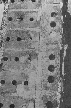
Pic. 6
Severe problems have developed in some buildings of the first generation of stone curtain walls, primarily the displacement of coping stones in the parapet and face panels on the wall. Removal of the stones reveals the cause of these problems, one of which is frost action in the backup masonry (Pic. 6). In some instances the backup units were saturated and badly spelled, and were no longer able to support the cramps locking the facing stone to the wall. In other instances, mortar “slushed” between the backup and the stone, was the site of the frost action which gradually pried the stones loose. In other cases cramps were corroded. In many cases, the moisture necessary for these two mechanisms to work came, not from the outside in the form of precipitation, but from the inside, accumulating in the wall in the form of condensation supplied by the outward leakage of warm humid air. The need for airtightness was hardly recognized by earlier designers, and the situation has since been exacerbated by the subsequent trend towards maintaining higher temperatures and relative humidities during the winter.
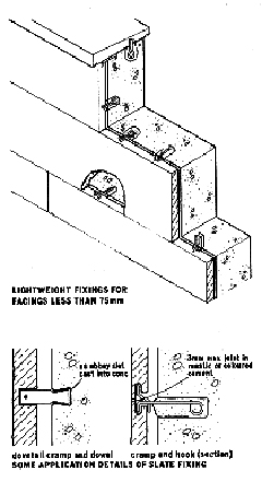
Pic. 7
Thin stone slabs, often of slate, have been attached to the face of buildings with masonry backup walls in an extension of the old techniques of stacking one unit above the other. Dead load stresses are transmitted through the thin edges of the stone slabs to the floor (Pic. 7*). The fasteners are often made of soft copper or bronze rods set in plaster of Paris or other cements; sometimes these cements are subjected to frost action when water penetrates the joints. The slabs are subsequently loosened and must be reset.

Pic. 8
In some instances metal fasteners transmit the dead loads of the stone slabs directly to the structural wall made of cast-in-place concrete or other masonry (Pic. 8*). Such fasteners must be heavier and stiffer than those in the previous example, especially when thick layers of insulation are required. These heavier fasteners must also be designed to allow thermal-induced movements to occur in the stone without restraint; otherwise concentrated stresses may lead to breakage of the thin stone slabs.
One development has been the use of thin stone slabs as surface finishes for precast concrete. Cement mortars and epoxy resins, with or without mechanical fasteners, and casting of concrete directly against the back of the stone, have all been used to attach stone to concrete, and with some success. However, there are examples of cracking of the stone or failure of the bond between stone and concrete caused by differential movement between them, due to shrinkage of the concrete, differential dimensional responses to temperature change or concentration of stresses at the mechanical fastenings.
One rather serious problem related to the use of thin stone veneers has arisen with white marble, of which the Italian Carrara is the most famous. On several buildings the panels have bowed visibly after only a few years of service and in some buildings, such as the new Finlandia Hall in Helsinki, distortion of panels in the windowless areas of the wall is pronounced.
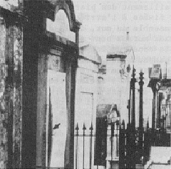
Pic. 9
White marble has a high content of pure calcite, differing from other marbles that also contain the mineral dolomite, a double carbonate of both calcium and magnesium. The crystalline structure of the two minerals differs in that the calcite (calcium carbonate) exhibits perfect cleavage planes in three directions. Dolomite has only two, which are less well defined. This imparts to the marble a creep behavior, which occurs even at low stresses, so that the material can flow under load. A comparison of stress/strain curves of various rock types makes this quite evident. The Romans apparently knew something about this; evidence of it can also be seen in old cemeteries, where thin slabs of marble attached to other stones have slumped under their own dead weight (Pic. 9).
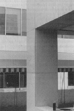
Pic. 10
Marble panels have become both concave and convex. Some have bowed along the horizontal axis, some along the vertical axis, but the patterns are usually uniform on any one type of construction where the panels are all attached to the building in the same manner. In part of a building that was examined (Pic. 10), the convex bowing of many panels was observed only five years after construction. At one place a 30-mm-thick panel had bowed 18 mm, more than half its thickness, over a height of 1.6 m. The manner in which most of the panels were attached indicates an eccentricity of load concentrated at the cramps or ties. If this explanation is valid, and the situation only deteriorates with time, both bowing and eccentricity will increase.
One relatively new development in the use of thin stone veneers that promises considerable savings in building costs is a prefabricated wall unit with precast concrete acting as the structural element. Insulation, air spaces and stone cladding are made integral and everything is manufactured under controlled conditions permitting designs of close tolerances.
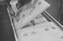
Pic. 11
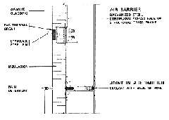
The stone panels are held to the structural concrete by various means, but most often by wire brackets sufficiently strong to bridge the space between them and take the load off the stone in shear without significant deflection. The brackets are positioned and attached to the back of the stone depending upon the size of the stone panel, which in turn is determined largely by the design of the wall unit and the size and spacing of windows in it. The wall units are assembled face down in the casting frame and the first step consists of positioning the window panel and the stone panels in the bottom of the form, with uniform perimeter spacing between them. In order to form an air space between the stone veneer and the insulation, spacers of some suitable material are placed at various locations on the stone panels, before the insulation is laid on top. If the structural design requires it, the supporting metal brackets may be embedded in concrete, passing through the outer surface of the insulation by holes cut through the insulation where they are located (Pic. 11). To prevent complete thermal bridges at these locations, closed cell insulating pads, the thickness of the air space, are placed before the laying of the insulation. After placing the insulation, which is usually a rigid plastic foam board, the joints are taped, the reinforcing steel is positioned and the concrete is placed.
Complete units are then cured, removed from the forms and stored. After transportation to the site they are fastened in place and sealed to each other or to the frame to form a suitable air barrier. This last stage is simply stated, but to be effective it must be executed carefully. Parts of the structure without windows can be clad with larger panels of the same stone installed manually after attaching fasteners to the cast-in-place concrete and covering the wall with insulation.
The advent of stone-faced steel truss curtain wall systems followed quickly on the heels of the precast systems, and it brought with it the promise of lighter loads and even higher buildings. Designers now speak confidently of 70- and 80-stores buildings constructed in this way and the major factor is the reduction in weight of the curtain wall to one-third or even one-fourth of the equivalent precast units. The major disadvantage, of course, is the higher cost of steel when compared to reinforced concrete.

Pic. 12
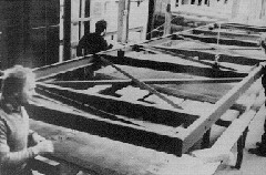
Some of the steel trusses are designed simply to support the stone stabbing but more sophisticated systems have developed incorporating both cladding and air barrier elements. Many of these new systems are basically spandrel panels with horizontal ribbon glass at each floor but the following example is a building designed with “punched” windows. Because of the constraints imposed by transportation, the whole wall unit, about 4 m high, was made in two parts: the spandrel panel and the window panel (Pic. 12). Unlike the precast concrete system, the window frames were not incorporated in the prefabrication process, a condition imposed by unions in the city where the building was erected.
The steel frame wall units are made in a similar manner to the concrete wall units in that they are also assembled face down, and the structural support is placed over the facing material. The stone panels are prepared by installing individual crank pins into obliquely drilled holes with epoxy cement and aligning them on a special frame. Here, sections of “z” bars are attached with a PVC material providing a thermal break between the bar and the stone. These fastenings are then carefully adjusted until they are all in the same plane ready to receive the steel spandrel truss. Glass fiber insulation is then placed over the stone.
Pic. 13
The trusses consist of various structural shapes, but are enclosed by a frame prefabricated of channels fitted together so that the edges are flat surfaces (Pic. 13). Angled sections are positioned on the trusses to support the stone panels and are slotted to receive the fasteners. The face of the truss is made airtight by the application of galvanized metal sheets over an edge seal held in place by power set rivets. Small holes are left in the metal sheets for the fasteners supporting the stone panels. The trusses are then lowered over the stone panels and insulation, and the connections are made to complete the units, making sure that the points of fastening are airtight.
At the construction site the system is installed on a steel structure with the columns set back from the edges of floors, allowing full access to the vertical and horizontal joints between the steel truss sections. The spandrel sections are attached to the column on brackets that take the vertical load of both spandrel and window sections. Adjustable fastenings at the columns and floors allow for horizontal positioning and transmission of wind and seismic loads. A neoprene strip is placed as a temporary weather stop at the outer face of the edges of the truss sections, but the whole system is made airtight by caulking at the inside between the steel channels which form the frames for the trusses.

Pic. 14
It is useful to review briefly the developments in design and construction techniques with stone that have occurred over the last one hundred years. Picture 14 is a very simplified diagram illustrating three main stages in the long process, which included many variations. Picture 14 is a traditional design developed in a part of Europe where the climate is much milder than in most of Canada. When massive-masonry was used for bearing walls, the stone was in simple compression with stresses carried from one unit to the other through carefully fitted dry joints or through the mortar. The weight of the roof was carried on the walls of the top floor. At the next store below, the walls had to pick up the load of the floor, and so on. The compressive stresses were normally very low because the thicknesses of the walls were proportioned for stability against sideways movements induced by wind and seismic loading, and these proportions had been developed through experience.
The exterior environmental conditions were no different from those experienced today but the massive walls were generally able to prevent the complete penetration of rain and frost. Thermal storage effects reduced interior temperature fluctuations in spaces that were heated only intermittently by wood or coal burned in fireplaces. Insulation was virtually unknown and humidity control was not even thought of. (And we have learned that imposing modern interior environments on these structures has sometimes caused considerable damage.)
Early masonry curtain walls (Pic. 14b) made possible by the introduction of structural frames were still quite heavy. Stone was attached to walls supported on the edges of floor slabs using metal cramps and bondstones or bricks but the stone had changed in shape. The blocks were now higher than they were deep, often in the form of heavy slabs presenting larger surface areas to the weather than previously. This had a tendency to reduce the area of Joints and should have reduced rain penetration, but was somewhat offset by the gradual elimination of cornices and other projections, which had acted to shed rain. The amount of stone used on the facade was reduced to perhaps a tenth of that used on a building of the same size with bearing walls.
Considerable changes had occurred and control of the interior environment came with the advent of central heating. After the Second World War, a need for insulation to reduce heat loses began to be recognized and a vapour barrier on the warm side of the insulation was introduced. Distribution of heat and other services throughout the building were arranged by providing spaces for pipes and ducts between the bottom of the floor slabs and a dropped ceiling. Plastering on the back of the masonry wall, which provided some measure of airtightness, was not carried above the false ceilings, and this section of exterior wall provided a relatively easy passage for air leakage. Better control of the interior environment included increased amounts of humidity in the air. This humidity leaking through porous sections of the wall, particularly at the top of the building, resulted in moisture condensation within the masonry, leaving it susceptible to damage when frozen and the metal cramp subject to accelerated corrosion.
Pic. 15
In the development of prefabricated wall units (Pic. 14c), the amount of stone used was again greatly reduced, to perhaps a tenth of that Clad in the first stone curtain walls. In the form of thin slabs with length-to-thickness ratios as high as 75:1, it has become a type of cladding and is no longer in compression (Pic. 15). In fact the slabs are deliberately isolated from one another to prevent this from occurring when increases in temperature and water content cause them to expand. The slabs are, however, now subjected to flexural stresses induced by wind and seismic forces, and it is precisely in this mode of stress that the stone is weakest. Typically, the flexural strength of stone is around 1/10 of its compressive strength, but it may be as low as 1/25 of the compressive strength. The fastenings must therefore be designed with great care: they must be sufficiently strong to take the dead load of the stone and sheer, and transmit the forces related to wind and seismic activity between the slabs and the structure, but they must at the same time be sufficiently flexible to allow dimensional movements induced by changes in temperature and water content to occur without significantly increasing the flexural stresses in the stone.
Rain penetration is prevented, or reduced, by sealing all of the joints with a caulking material between the edges of the stone slabs except at the window head or the flow lines where any water that does reach the back of the stone is deflected to the outside over a flashing. (It is interesting to note that mortar is no longer used around the stone in these units.) Separation of the exterior and interior environment is provided by sheet metal or concrete taking the wind loads and acting as the airtight element of the system, and by a blanket of insulation. Complete airtightness of the system, however, depends heavily upon the seals between the units so, where this is not done carefully, there may be air leakage with a potential for condensation and the buildup of frost and ice prying at the fastenings and loosening the veneer.
This article was published as part of the technical documentation produced for Building Science Insight ’84, “Performance of Materials in Use,” a series of seminars presented in major cities across Canada in 1984.